【简单介绍】
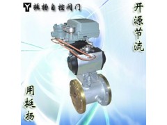
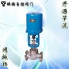
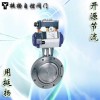
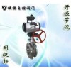
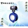
气动法兰调节球阀具有良好的保温保冷特性,且阀门的通径与管径一致,同时又能有效降低管路中介质热量损失。主要用于石油、化工、冶金、制药、食品等各类系统中,以输送常温下会凝固的高粘度介质。
【详细说明】
|
一.概述Product Overview:
气动法兰调节球阀具有良好的保温保冷特性,且阀门的通径与管径一致,同时又能有效降低管路中介质热量损失。主要用于石油、化工、冶金、制药、食品等各类系统中,以输送常温下会凝固的高粘度介质。
由于采用整体式结构,因而保温球阀比一般球阀何种更小,重量更轻,且无外漏,密封性能良好,夹套采用碳素钢管焊接比铸造的更加耐压牢固。根据管道需要,决定选用往复式(二位开关式)或弹簧复位式(常闭或常开式)。可选配控制附件:(1)单电控电磁阀(断电进常闭或常开),(2)双电控电磁阀(开关式),(3)阀位开关回讯器,(4)气源处理三联件。特殊使用环境(易燃易爆场合),何选防爆型。
Pneumatic flange ball valve with good thermal insulation characteristics of cold, and the diameter of the valve diameter and the same, while the media effectively reduce heat loss in the pipeline. Mainly used in petroleum, chemical, me-tallurgical, pharmaceutical, food and other types of systems will be solidified at room temperature in order to transport high-viscosity media.
As a result of the overall structure, and thus what kind of insulation ball valve than smaller, lighter, and no leakage, good sealing performance, the use of carbon steel welded jacket casting more pressure than solid. According to the pipeline needs, decided to use reciprocating (two switch-type) or spring return (normally closed or normally open). Optional control accessories: (1) single electronic control solenoid valve (normally closed or normally off into the open), (2) double solenoid valve (switching), (3) Limit switches back to the hearing, (4 ) triple gas source processing parts. Special use of the environment (explosive situation), what selection explosion-proof. |
二.技术规范Technical Specifications:
|
|
ASME B 16.34 GB/T12224
|
|
|
ASME B 16.10 GB/T12221
|
|
|
ASME B 16.5、JB/T 79
|
|
|
手动、电动、气动
Manual, electric, pneumatic
|
|
|
JB/T9092 API 598
|
|
|
重油、胶类等易凝固介质
Heavy oil, rubber etc. easily solidified media
|
|
三.主要零件材料Materials for main parts:
|
|
|
材质
|
|
C
|
P
|
R
|
|
1
|
|
25
|
SUS304
|
SUS304
|
|
2
|
|
WCB
|
SUS304
|
SUS316
|
|
3
|
|
25
|
SUS304
|
SUS316
|
|
4
|
|
|
|
5
|
|
SUS304
|
SUS304
|
SUS316
|
|
6
|
|
1Cr13
|
SUS304
|
SUS316
|
|
7
|
|
|
|
8
|
|
WCB
|
SUS304
|
SUS316
|
|
四.主要外形尺寸Main dimensions:
|
公称通径(DN)
|
d
|
L
|
D
|
E
|
Q
|
H
|
W
|
|
|
(mm)
|
(in)
|
(mm)
|
(in)
|
P
|
|
20
|
3/4"
|
19
|
117
|
40
|
1 1/2"
|
58.5
|
147
|
101
|
170
|
G3/4"
|
|
25
|
1"
|
25
|
127
|
50
|
2"
|
62.5
|
156
|
106
|
170
|
G3/4"
|
|
40
|
1 1/2"
|
38
|
165
|
65
|
2 1/2"
|
63.5
|
181
|
125
|
250
|
G3/4"
|
|
50
|
2"
|
51
|
178
|
80
|
3"
|
68
|
218
|
135
|
250
|
G3/4"
|
|
80
|
3"
|
76
|
229
|
150
|
6"
|
82
|
275
|
193
|
350
|
G3/4"
|
|
100
|
4"
|
102
|
254
|
200
|
8"
|
83
|
300
|
265
|
420
|
G3/4"
|
|
150
|
6"
|
152
|
292
|
250
|
10"
|
95
|
403
|
355
|
1000
|
G3/4"
|
|
200
|
8"
|
203
|
330
|
300
|
12"
|
100
|
495
|
410
|
1300
|
G3
|
|
